74AC04 Residual Phase Noise Measurements
February 26, 2010

Notes:
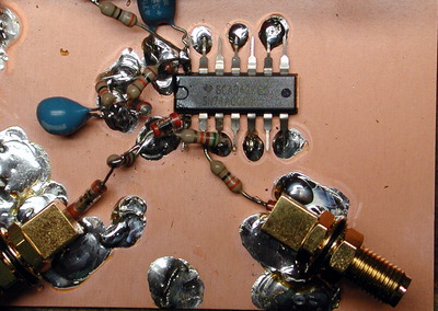
- Residual noise tests were conducted on a TI SN74AC04N with HP 3048A system at 10 and 100 MHz. Topology was similar to that used elsewhere, but with higher source amplitudes.
- Test source was HP 8642B with SCLF-10.7 and PLP-150 low-pass filters ahead of the splitter, depending on measurement frequency. Similar filters were used at the output of the 74AC04 circuit to keep harmonics out of the 3048A system.
- The measurement floor at offsets between 10 and 100 kHz was better than -170 dBm at all frequencies and power levels tested. Above 100 kHz, decorrelation of broadband noise from the test source contributed to degradation in the measurement floor. For this reason, the plots below are valid primarily below 100 kHz.
- Circuits tested were derived from figures 3-2 and 3-3 in the Datum LPRO-101 manual (1.6 MB .PDF).
- One drawback to the use of a 74AC04 as an amplifier is that it needs about 1.8 volts pk-pk to 'toggle', regardless of input frequency. At 50 ohms this is about +10 dBm.
Instead of feeding the inverter directly from a 50-ohm source, it's helpful to use an 8:1 broadband transformer to supply some voltage gain. The circuit at right reflects this modification.
- As in the Datum example circuits, the "self-bias" configuration used a 51K resistor across the inverter, with the fixed bias network disconnected. No significant differences in phase noise were noted
with the self-bias resistor in place.
- Power supply was an HP 6284A that's known to be reasonably quiet. Vcc at pin 14 was about 4V. It's possible that further improvement in the residual floor could be obtained
with a cleaner supply, but it's more likely that input amplitude will be the limiting factor in any application where the chip is used as a sine-to-square converter.
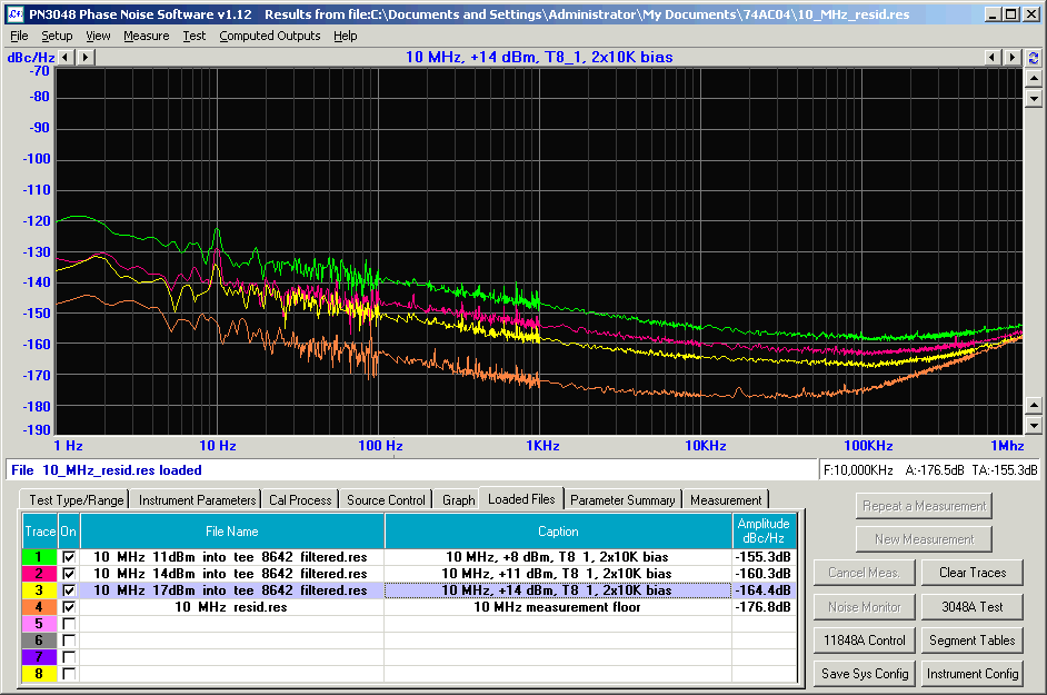
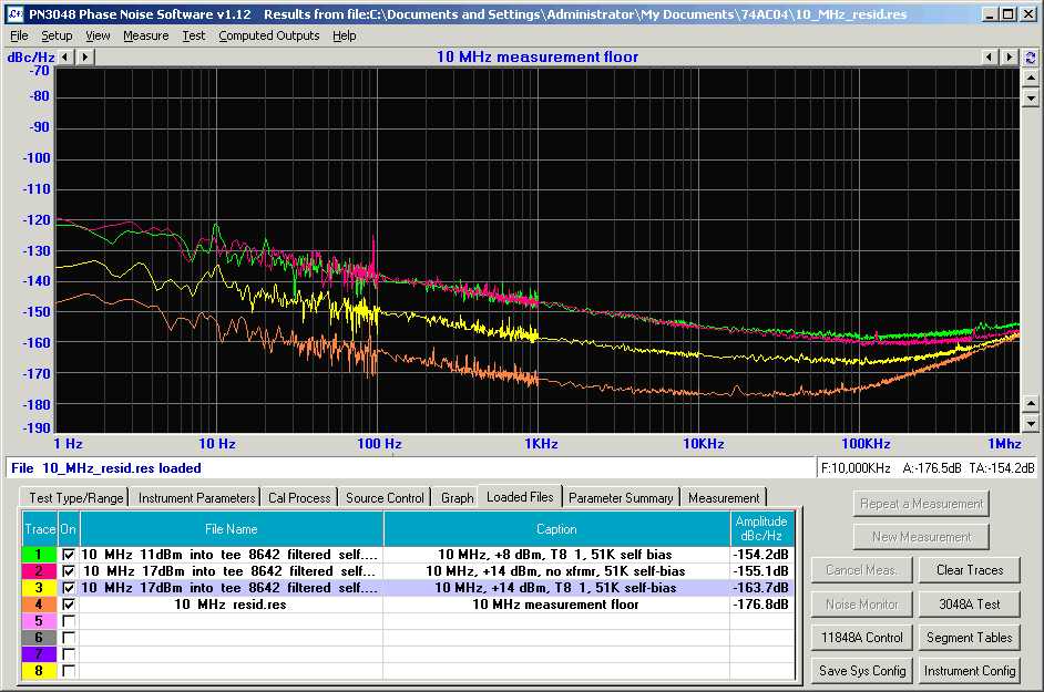
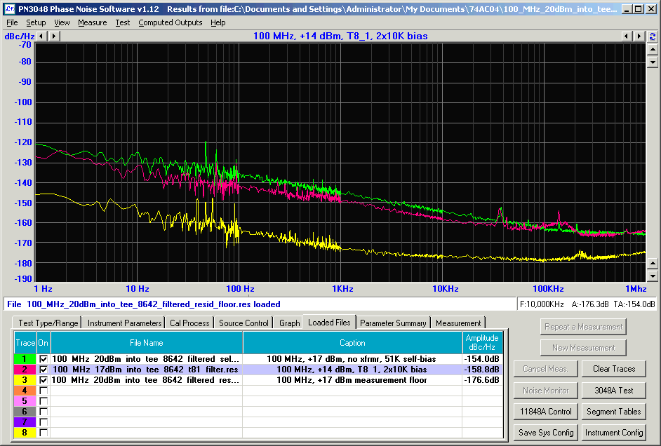
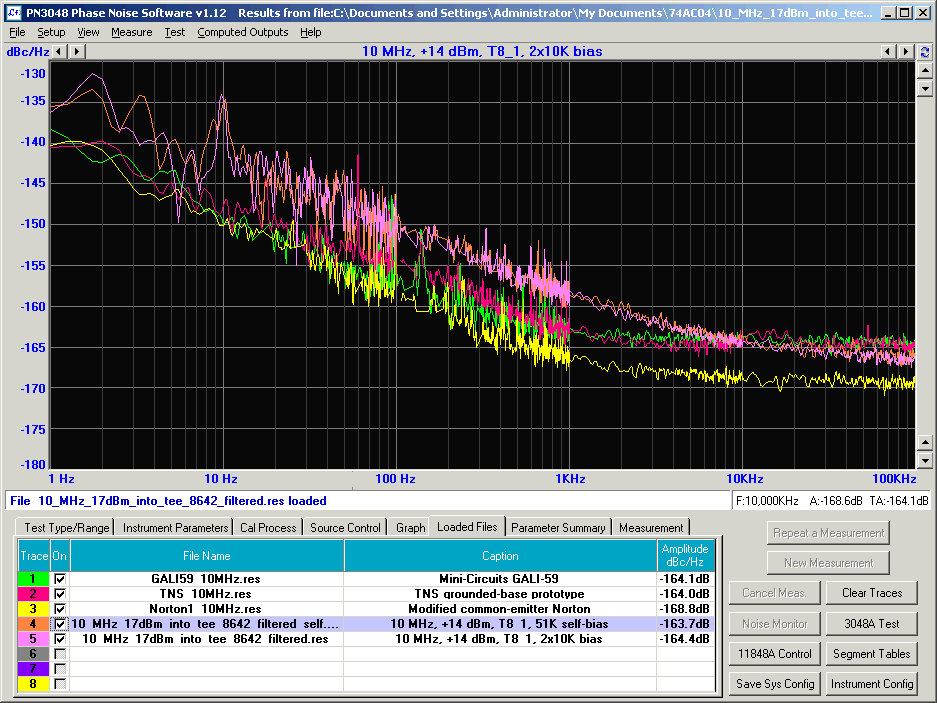
Finally, a comparison of the self-bias and fixed-bias connections appears below, with the respective orange and violet traces almost indistinguishable from each other. The green, red, and yellow traces are
from earlier measurements of various 10 MHz amplifiers.
Back to John Miles, KE5FX home page
Text copyright © 2010 John Miles. All rights reserved.


